Prototype Setup
The setup of a prototype of the Solid State Mass Memory is shown below.
The photo shown were taken at the microelectronic laboratory of Electronic Engineering Department.
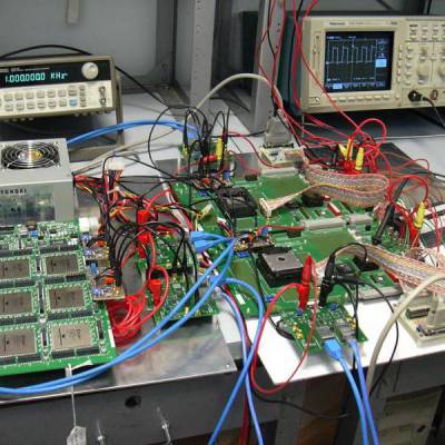
In photo 1 the setup of dynamic router and Spacewire interfaces is shown. The main building blocks of this setup are one plate implementing the dynamic router and two plates implementing the Spacewire/Personal Computer interfaces. In this setup the two memory modules are not shown. On the plate implementing the dynamic router (on the left side of photo 1) are mounted:
- One Dini DN2000K10 board mounting six Virtex 1000 BG 560 FPGA's (photo 2)
- Two National LVDS47/48EVK Cards mounting the LVDS TVTTL conversion buffers (photo 4)
- A 250 W power supply unit
On each of the two boards implementing the Spacewire/Personal Computer interfaces (on the right side of photo 1) are mounted:
- One Xilinx HW-AFX prototyping board mounting a Virtex II XC2V3000 FPGA (photo 3)
- One National LVDS47/48EVK Card mounting the LVDS TVTTL conversion buffers (photo 4)
- One PCB mouning the buffer circuitry for interfacing with PC parallel TTL port level signals
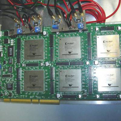
The Dini board is a fast prototyping board which can include up to 6 Virtex 1000 FPGA's. The overall amount of equivalent gates can be approximated to 6 millions. In the SSMM design the board has been used to implement most part of the designed logic including the dynamic router the link and memory interfaces and the microcontroller. The Dini board interfaces are two spacewire ports carried on LVDS (using National LVDS47/48EVK Cards) links toward the users and two memory ports toward the memory modules.
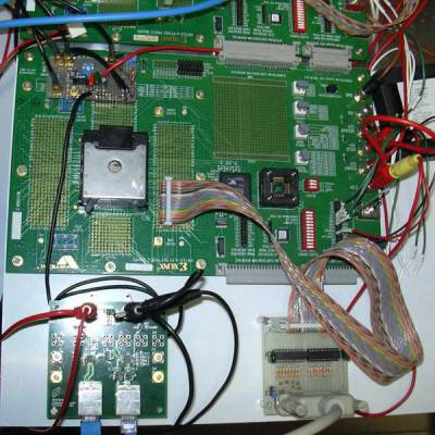
Each HW-AFX board mounts a Virtex II XC2V3000 FPGA. The implemented logic on each FPGA is the same. These boards allow the interfacing of the Personal Computers and the SSMM. For this reason, on each board a parallel port interface and a Spacewire interface are implemented. The Spacewire port uses a National LVDS47/48EVK Card to convert the LVTTL signals to the LVDS required from the Spacewire standard
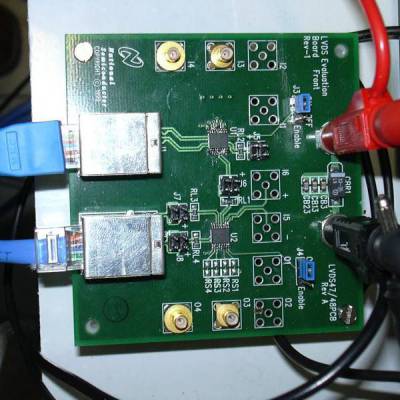
A total number of four National LVDS47/48EVK Cards has been used to implement the prototype setup. Each board mounts two chips: a LVDS line driver with 2 differential channels and a LVDS Receiver with two differential input channels. The differential signals are sent and received by means of two RJ45 CAT 5 cables.